electronic speedometer conversion
I found this conversion on Dylan Parker's website evmini.ca. This was done because of an engine and transmission swap so it's probably not necessary for an average Mini, but I found this genius and wanted to share. All content and pictures are from Dylan's website.
SpeedHut was the only company I found that could give me a small programmable gauge that went from 0 to 150 km/h across a 240° sweep. The company was incredibly helpful in answering questions and I’d highly recommend them to people needing programmable gauges.
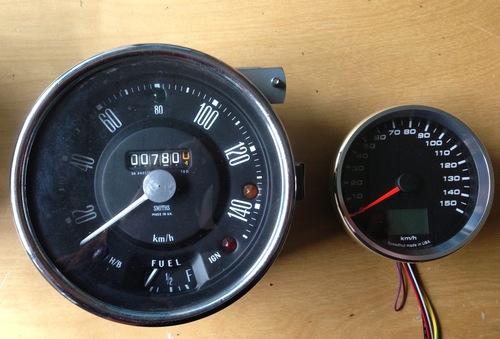
Here is the SpeedHut 3-3/8" speedometer beside my Mini speedometer.
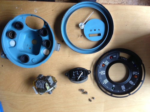
I disassembled the Mini speedometer. A few crimped edges, some screws and it all comes apart.
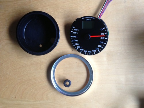
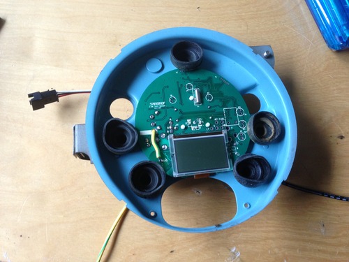
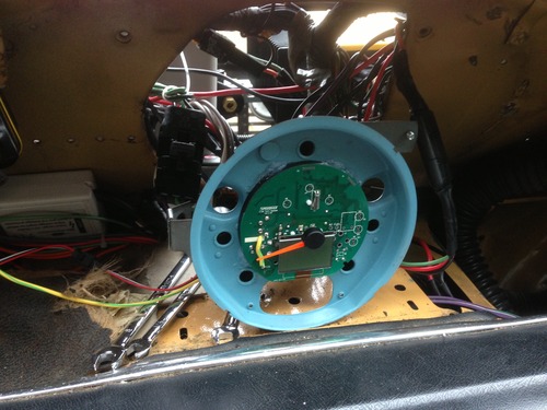
Then I disassembled the SpeedHut gauge and tested if it would fit within the Mini enclosure while keeping the needle centered and not blocking lights and fuel gauge etc.
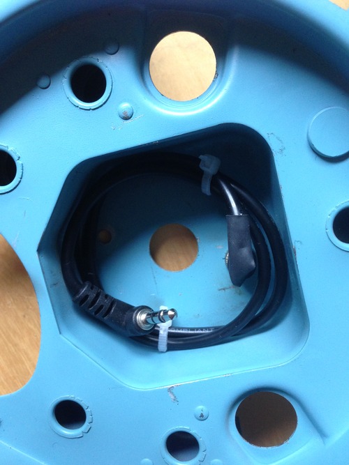
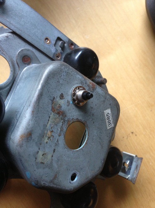
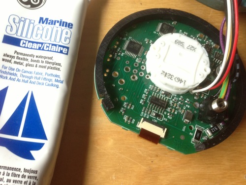
The SpeedHut gauges can come with a button on their face, or on the end of a cable that plugs into the back of the speedometer. I opted for the back and found I could nicely coil the cable in the rear of the Mini enclosure and then mounted the button through one of the old mounting holes. I don’t plan on using that button (except for initial calibration) but left it handy just in case.
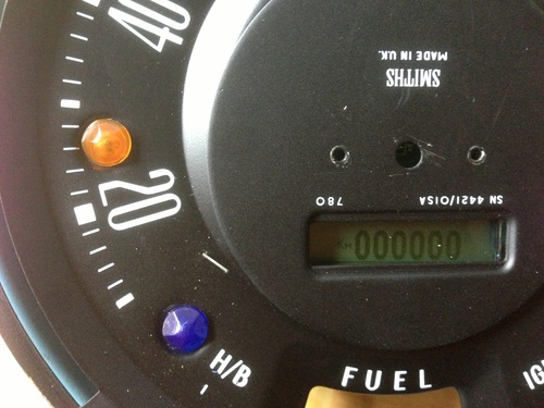
After loosely centering the electronic speedo, I replaced the Mini faceplate to see where the odometer LCD would sit. I knew the SpeedHut gauge had the odometer below the needle and the stock Mini odometer is above needle, but I hoped I could just rotate the center disc and have it lineup.
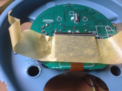
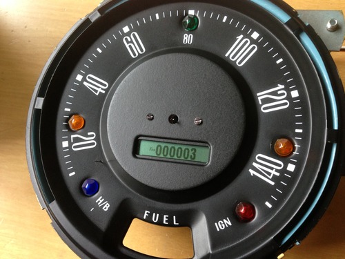
At first it looked plausible, but then after powering up the Speedometer I discovered the odometer was about 10px lower on the LCD than I needed. The window didn’t line up. In the photo below, the middle disc is rotated and moved a fair bit off-center to get the odometer visible.
At first it looked plausible, but then after powering up the Speedometer I discovered the odometer was about 10px lower on the LCD than I needed. The window didn’t line up. In the photo below, the middle disc is rotated and moved a fair bit off-center to get the odometer visible.
The SpeedHut gauge also has a trip meter below the odometer, but to make that viewable would mean widening the window or fabricating something new. I wasn’t concerned about the Trip meter.
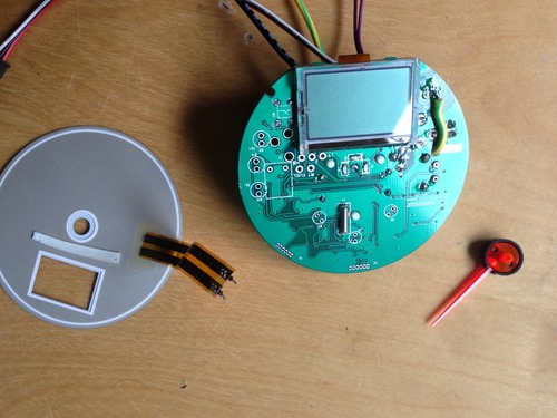
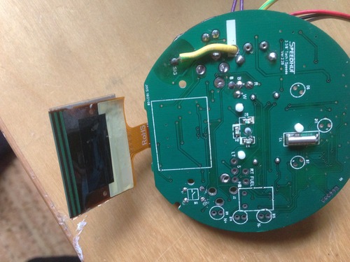
I mulled for a bit, then decided I’d unsolder the LCD from the Speedometer to see how much play there was in positioning. I discovered that the LCD has a small ribbon cable for data and the main soldering is to power the LCD backlight.
After some more mulling, and some tests I decided that I didn’t want or need the LCD to ever be lit (the Mini speedo has backlighting already) and so boldly decided to remove the backlight from the LCD completely. The backlight panel is quite bulky and with that out of the way the LCD now had enough play to slide closer to the needle and allow for correct alignment through the rotated Mini odometer window.
I used some silicone to securely stick the LCD exactly where I wanted it and let that dry.
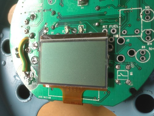
With the backlight gone, the LCD panel was now quite inset behind the odometer window. I wanted the LCD brought closer to the speedometer face. The SpeedHut gauge came with a plastic spacer that, amazingly, was perfect to raise the gauge off the back of the Mini enclosure to bring it flush with the odometer window. Nice!
I siliconed the spacer to the gauge then siliconed them both to the back of the Mini enclosure making sure to get the needle exactly centered.
I siliconed the spacer to the gauge then siliconed them both to the back of the Mini enclosure making sure to get the needle exactly centered.
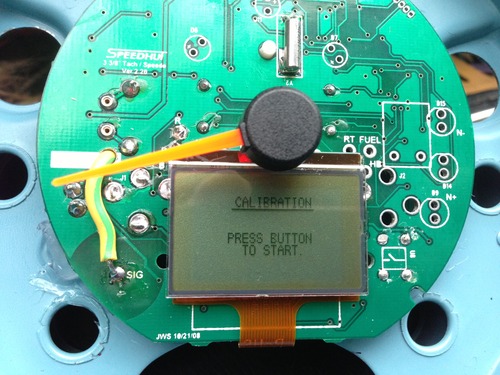
I was feeling pretty confident at this point, so decided I should calibrate the Speedometer while the screen was fully visible.
Calibration is done by hooking the speedometer up to your vehicle speed sensor and then putting the speedometer into ‘calibration’ mode. You then drive exactly 4km and stop the calibration. The speedometer tallies the number of pulses it saw and can now give you an accurate speed reading.
Rather than mapping out a route, I used the Odometer+ iphone app to tell me when I’d driven exactly 4km. Easy peasy.
The calibration went well, and the needle seemed to be reacting appropriately for the rest of my drive home. I say 'seemed to’ since I didn’t have any speedometer face on during this calibration. In retrospect, once I was pretty sure the speedometer was going to work for my needs, I could have done the calibration before the integration got too far along.
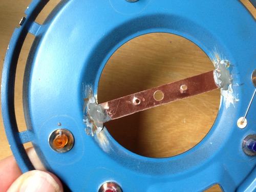
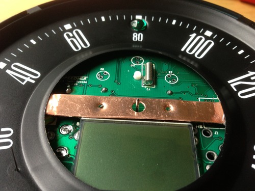
Before final assembly, I needed a way to attach the the center disc to the speedometer face. In the original setup, the disc was fastened to the mechanical internals with two small bolts. I decided to attach a piece of copper across the face for the front disc to bolt to. In retrospect this was unnecessary – I could have just siliconed it permanently and placed the bolt heads there for show – but it made sense at the time. The end look is the same.
The center disc, now rotated, has all of the white lettering upside down. So before attaching the center disc with the two bolts, I gave it a spray paint with some matte engine enamel I had lying around. The colour and texture is not identical but I’m pretty happy with the end result. Yes I lose the text, but I couldn’t think of an easy way to keep it. Also, I think the gauge looks nice and clean without it.
Before final assembly I also gave the needle a new paint, cleaned up the glass, polished the chrome, re-attached the bottom fuel gauge and then put it all back together.
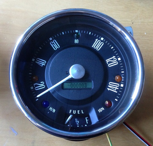
I am very pleased with the result of this custom conversion. It really wasn’t that difficult in the end, but I definitely got lucky with how well things pieced together. Here is the fully assembled speedometer.
I am very pleased with the result of this custom conversion. It really wasn’t that difficult in the end, but I definitely got lucky with how well things pieced together. Here is the fully assembled speedometer.
