rewiring
This is less of a tutorial and more of a chronicle. This is courtesy of Jeff Meade aka jeffm5150 of North American Motoring.
Original images taken from http://desertwave.com/gallery2/main.php?g2_itemId=5582
Original images taken from http://desertwave.com/gallery2/main.php?g2_itemId=5582
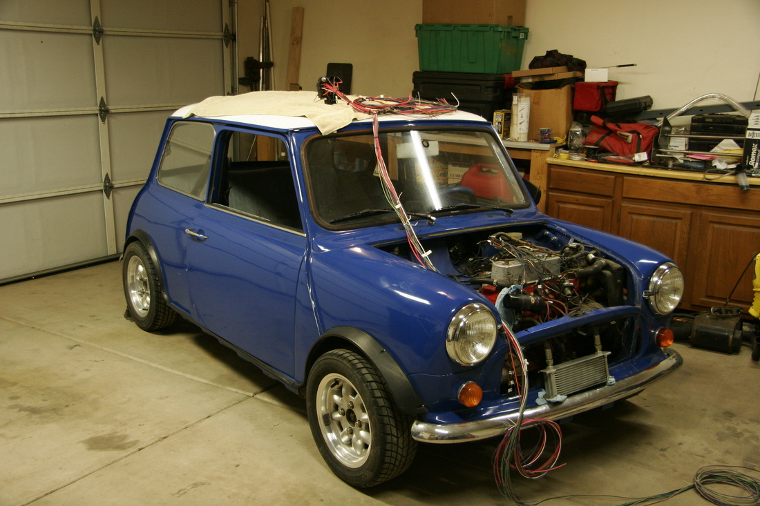
Here's the new wiring harness and fuse block laid out on top of the car. The wires hanging into the engine compartment are for the engine and headlights. The ones coiled over the left top side of the car are for inside the dash like turn signal switch, ignition switch, etc. There's another bundle of wires thrown over the back of the car for taillights and stoplights.
I mounted the fuse block between the pedals and left kick panel. I used a piece of 1/4" thick aluminum L-bracket to mount the block to the dash structure.
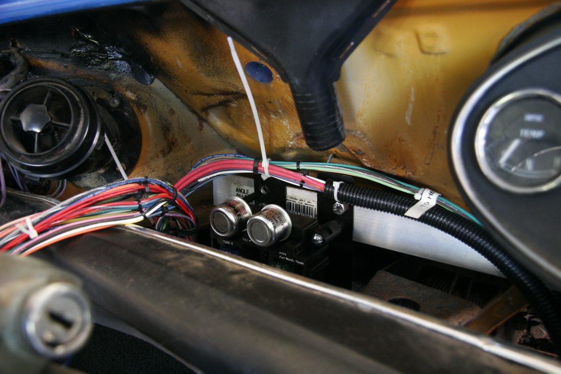
zA close up of the fuse block installed. The wires hanging out to the left will be for the dash, ignition switch, turn signal switch, and tail lights. The wires running over the top of the fuse block are for the engine and headlight circuits, and will pass through the firewall.
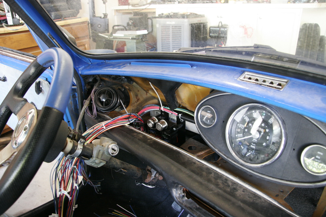
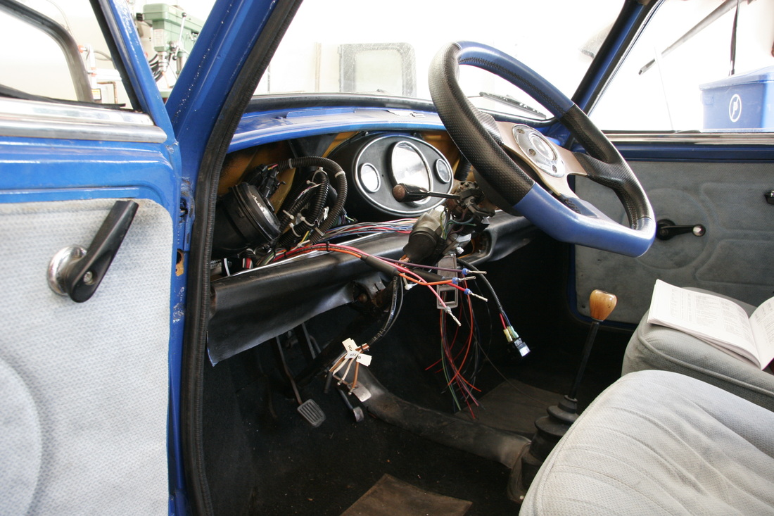
Here's a wide view of the wiring harness as it's starting to be installed. The fuse block is mounted, and the wire bundles are awaiting routing and connection

This shows the fuse block installed from the underside. The dash will be covered once this is complete, so the fuses and flashers need to be accessible.
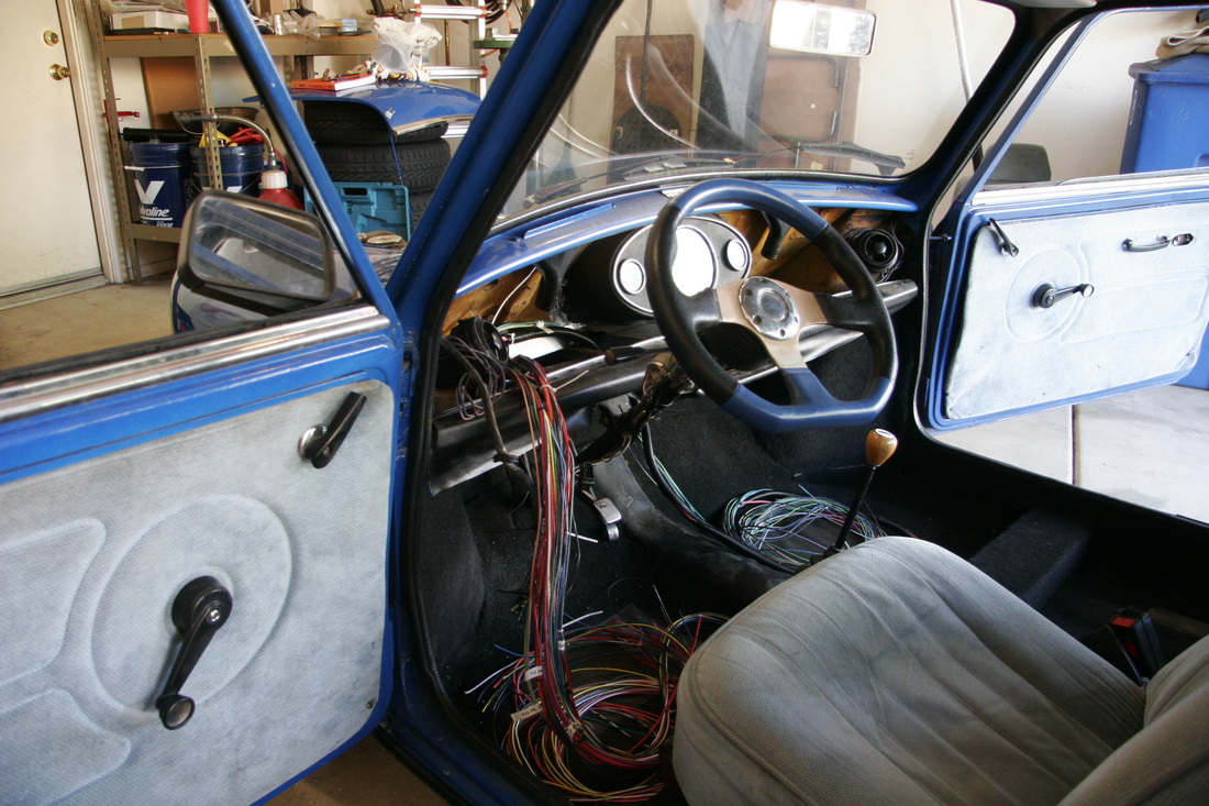
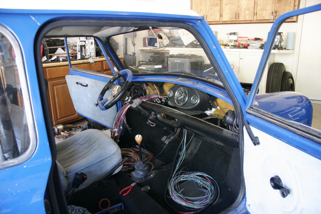
This is a view of the install from the left. The large bundle of wires hanging out the dash will ultimately be connected to the ignition switch, turn signal switch, tail lights, and dash connections.
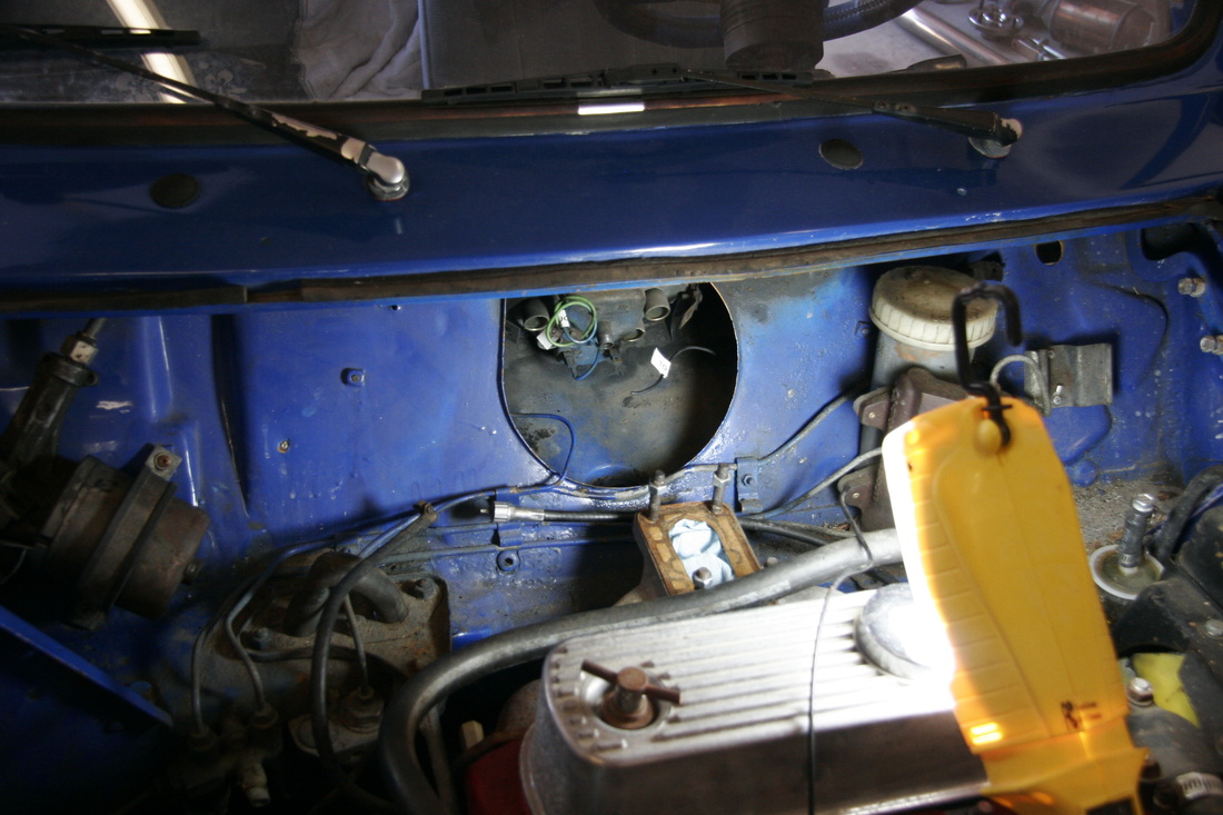
This is a view of the engine area prior to running wires out from the cabin. The factory wires leave the cabin at the bottom of the large opening on the firewall. This area was covered in wires with the factory harness.
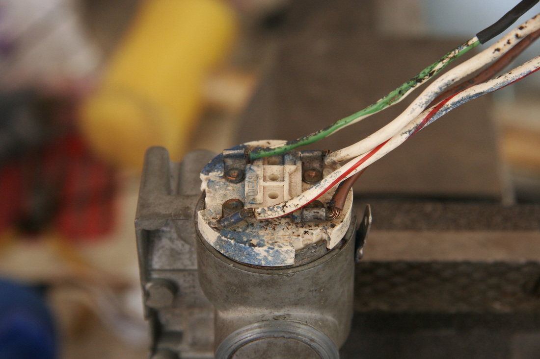
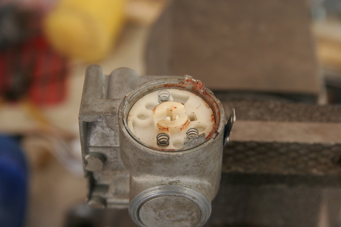
This is the old (original?) ignition switch. The wires need to be replaced since there appears to have been a short in the green/white wire (accessory power) wire sometime in it's past. The wires are not replaceable since they are rivited through the white plastic switch piece. Since neither new nor replacement ignition switches are available for this '73 Mini, I decided to buy an ignition switch for a 1974 MG Midget. The needed wiring parts are identical, as seen in the following pictures.
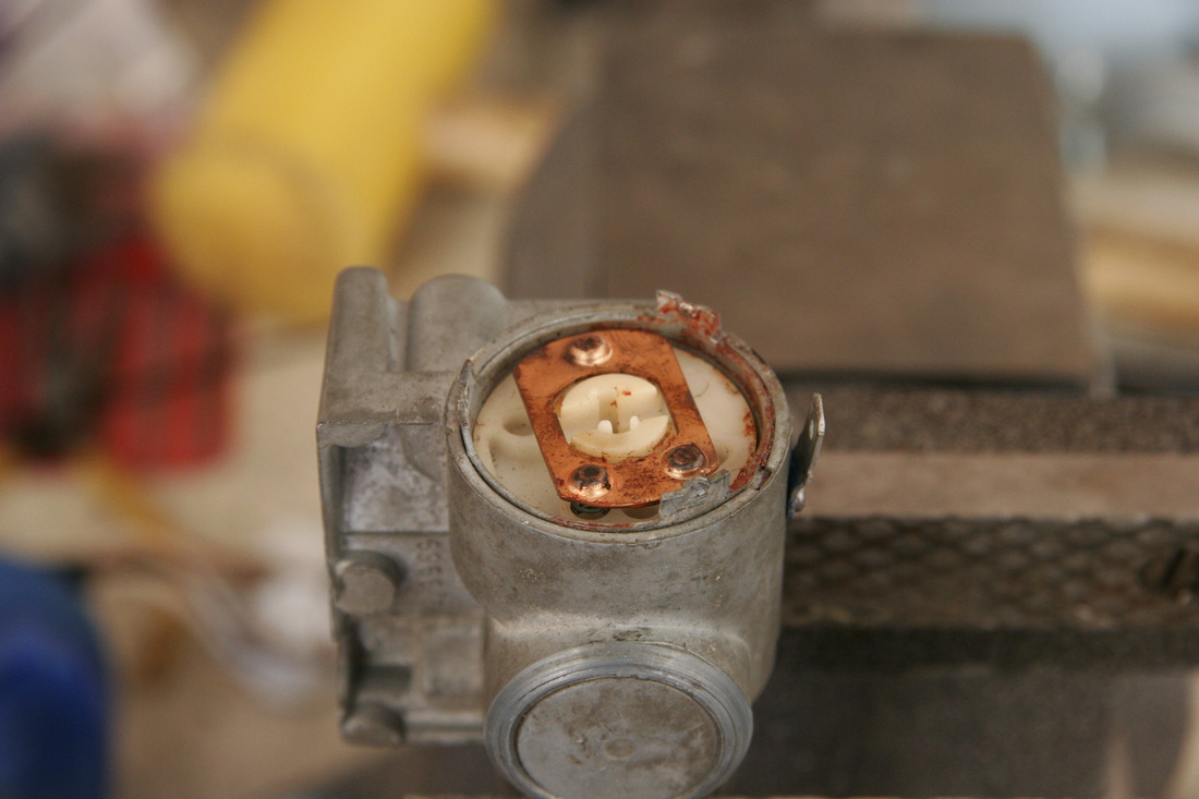
The plastic wiring piece of the ignition switch is removed. The three tabs extending away from the switch body were bent out to allow removal of the plastic piece containing the wiring.
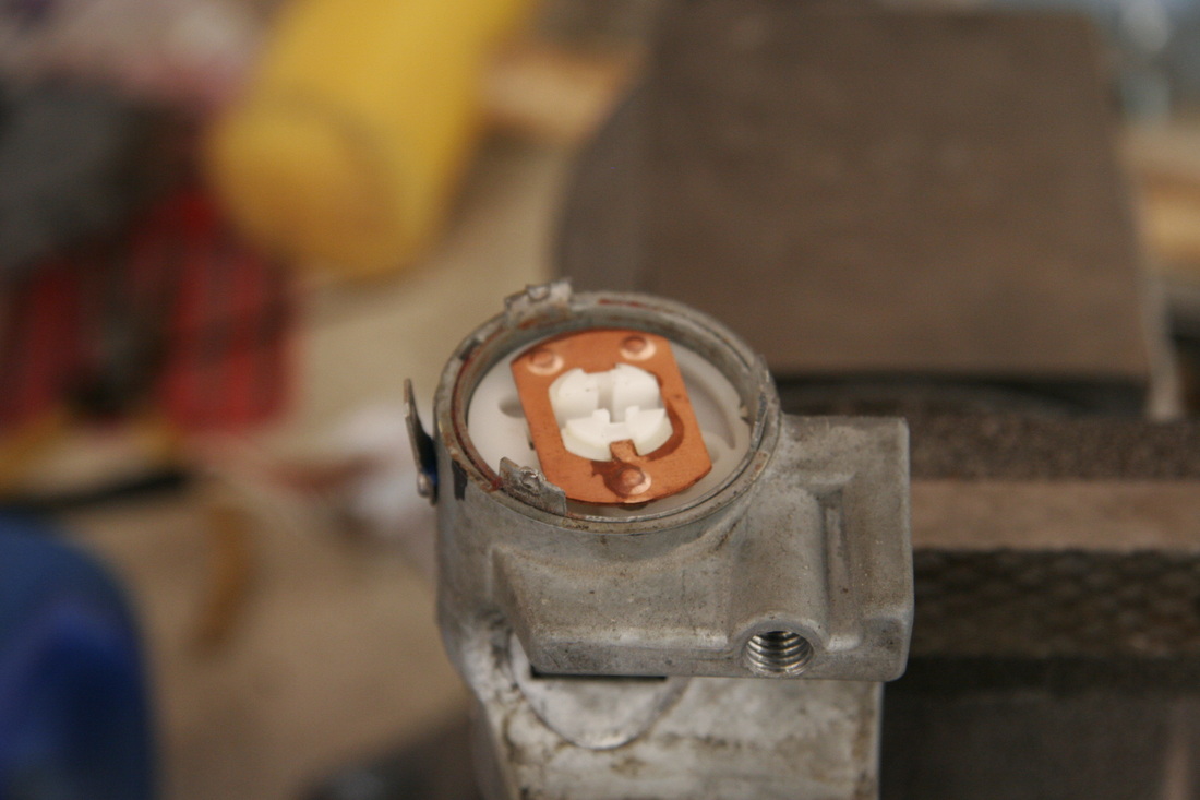
The metal shorting bar is removed to expose the rotating switch assembly that is turned by the key cylinder. The springs allow good electrical contact with the contacts.
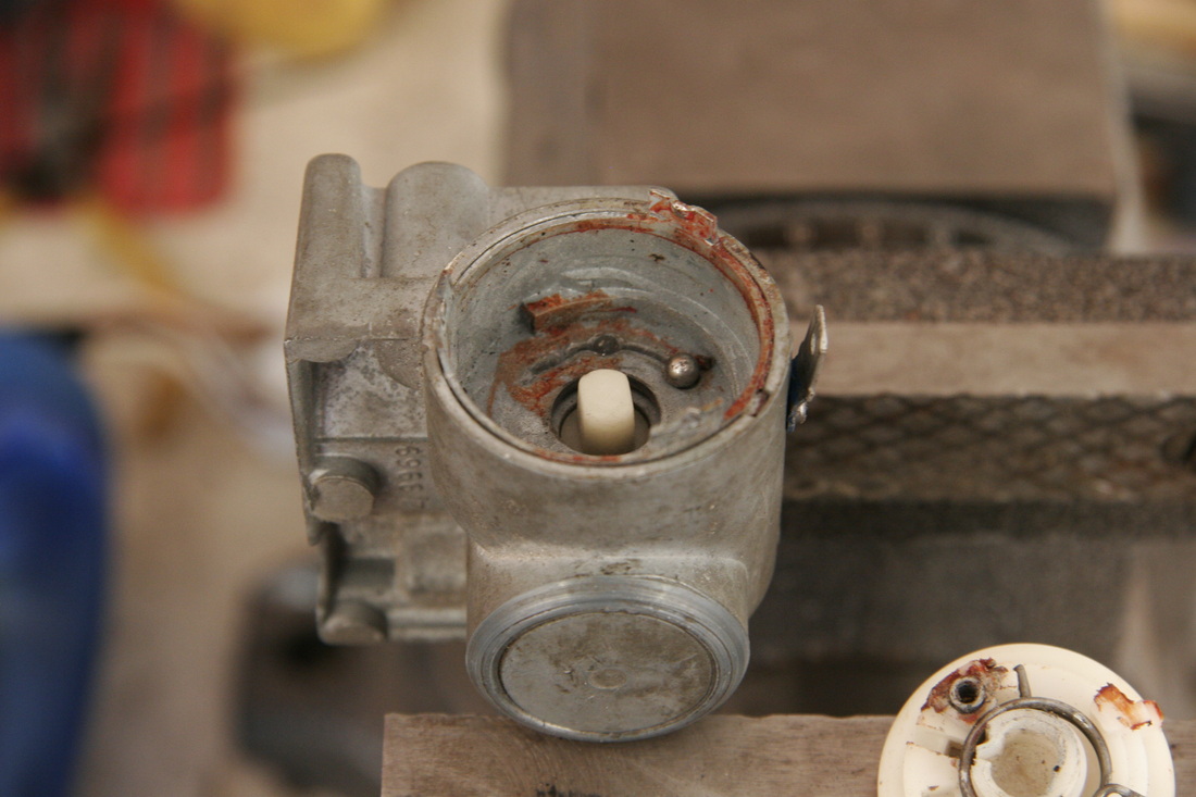
The rotating switch assembly is removed. There is a ball bearing inside the switch housing that provides the detents when moving the key from OFF/IGNITION/START. Similar to the shorting bar, the switch assembly rides on the ball bearing with a spring which provides a positive feel when turning the key.
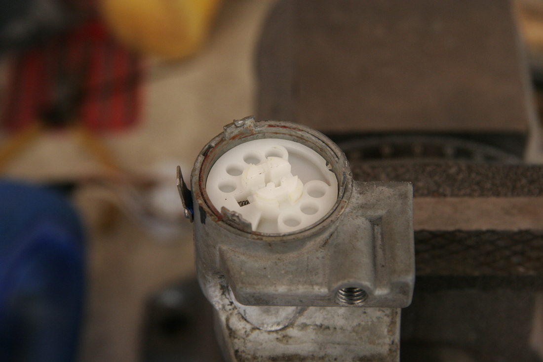
The internals from the doner MG Midget ignition switch are now swapped in.
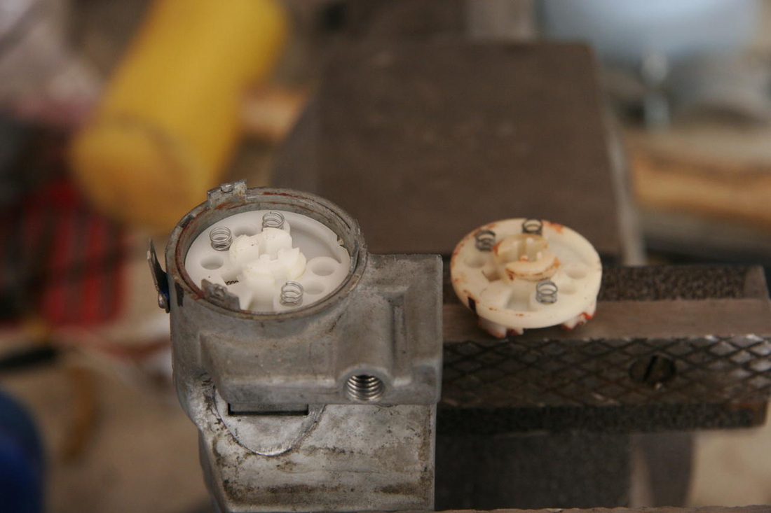
The shorting plate springs are added to the rotating assembly. Note the old rotating assembly in the background.
The shorting bar is added to the rotating assembly. This required a bit of futzing with the metal piece, as it clips onto the plastic. Nothing a little force can't solve.
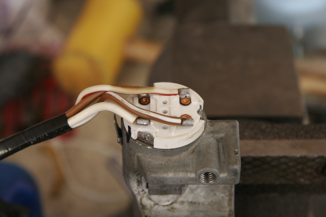
Here's the completed assembly. The only moving parts not swapped out are the key cylinder parts. A couple of notes: (1) with the exception of the green/white wire, the wire colors between the Mini and MG Midget ignition switch are the same, and (2) the green/white IGNITION wire in the old switch is now replaced with a much larger gauge brown/white wire.
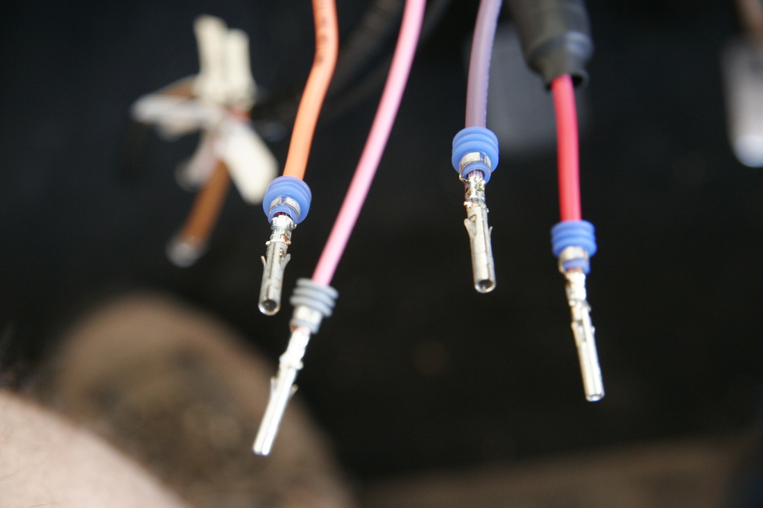
These are the ignition switch wires coming from the fuse box destined for the column-mounted ignition switch. The wires have been cut to length, then the WeatherTite ends crimped on to the wire. Once crimped, the wires were soldered to the ends to make sure the ends would not come off. The blue (3) and grey (1) rubber seals between the crimped ends and the wire insulation keep debris out off the connections. The blue are for the 12 gauge wires and the grey is for the 14 gauge wire.
This shows the wiring prior to completion. The red/orange/pink/purple wires come from the fuse box. The brown/white labeled wires come from the switch. Note the large black objects inline in the red and orange/brown wire sets. The new wiring harness has two 12 gauge wires to connect to the ignition switch for BATTERY+, one 12 gauge wire for IGNITION, and one 12 gauge wire for ACCESSORY. Since this ignition switch has only a single 12 gauge wire for BATTERY+, and a single 12 gauge wire for ACCESSORY/IGNITION, the two red wires were spliced together using a POSILOCK (tm) wire splice. Similar for the 12 gauge ACCESSORY and IGNITION wires. Once spliced, the POSILOCK splices were shrink wrapped to ensure they would be protected from shorting if ever they came apart.
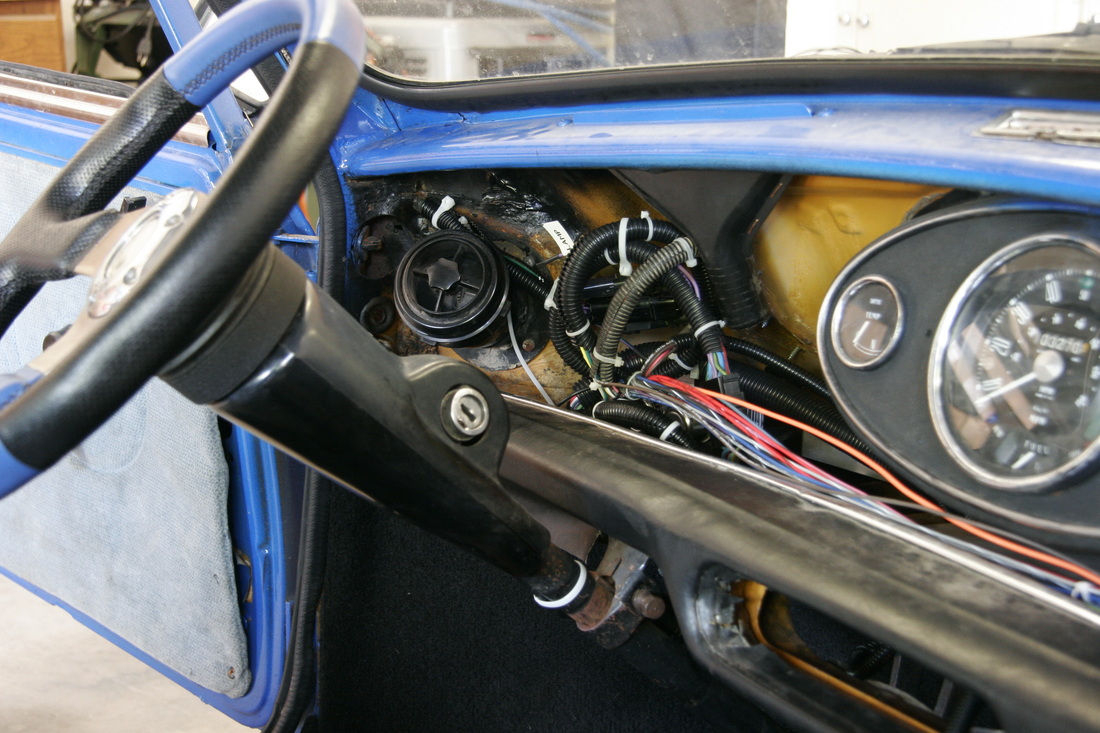
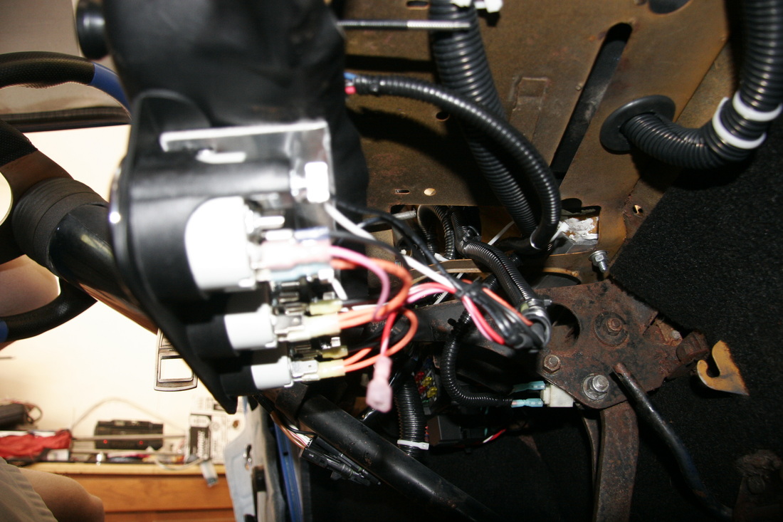
This shows the completed ignition switch wiring completed. The WeatherTite connector is seen at the bottom of the column directly under the dash.
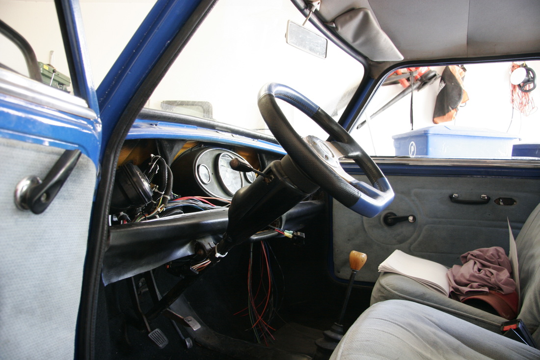
Here's another view of the reinstalled column shroud now that the wiring is completed. The mass of wires will all be covered by the dash face once reinstalled.
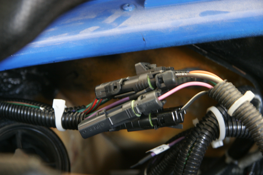
These connectors are for the tail section of the car, such as tail lights, rear turn signals, and rear parking lights. The connectors were used so that the wiring in the rear of the car can be completed at a later date. Again, WeatherTite connectors were used. One two-pin connector was used for the dome light, one four-pin connector was used for the tail lights, and one single-pin connector was used for the fuel gauge sender.
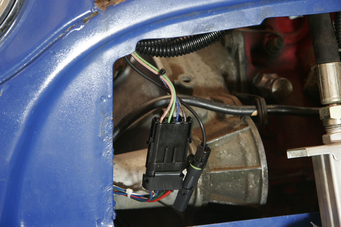
This shows more WeatherTite connectors used for the front lighting. This is the right-front corner of the car. Similar connections are on the left-front corner. The four-pin connector includes high-beam, low-beam, parking lamp, and turn signal. The single-pin connector handles the ground wire.
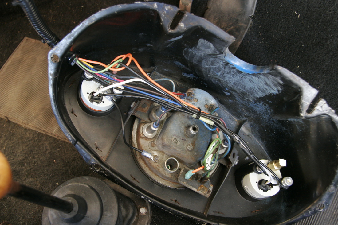
This shows the gauge cluster wiring with the cluster removed from the dash. From left is water temp gauge, then speedo, and indicator lamps, then oil pressure gauge (to be connected later).
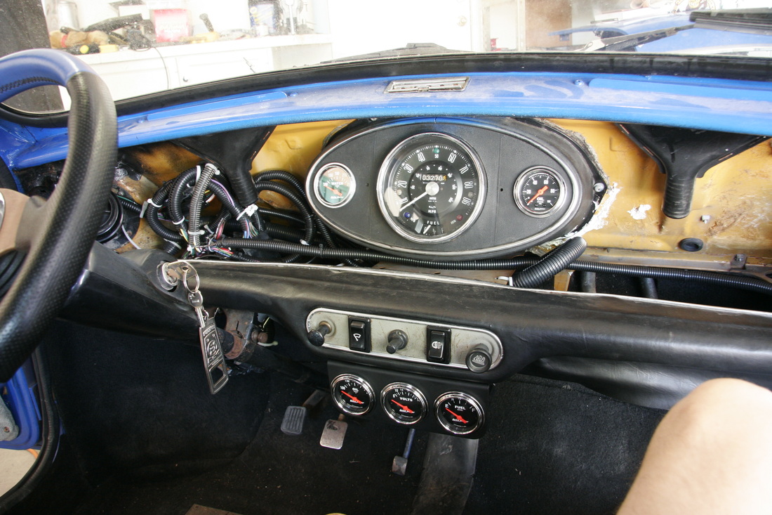
The result of the completed wiring of the cabin is shown here. The large oval gauge pod above is stock, but with new water temp and oil pressure gauges. The bottom gauge pod has three new gauges; oil temperature (not yet connected), voltmeter, and fuel level (not yet connected). The switch plate has (from left to right) choke, windscreen wiper switch, ejector seat button, headlamp switch, and heater controls. The choke and heater cables will be replaced with new cables later.
This is an under-dash shot to (poorly) show the gauges and wiring for the lower pod. Not as clean as I would like, but the mass of ground and lighting wires produces a fair bit of wire. The red/white wire that is disconnected is for the voltmeter. It's no longer connected since connecting it to the new gauge causes the gauge to display incorrect voltage. The voltmeter gets it's signal from ignition 12v, so only the orange wire is used. The brake switch can be seen in the background hanging from the pedal assembly
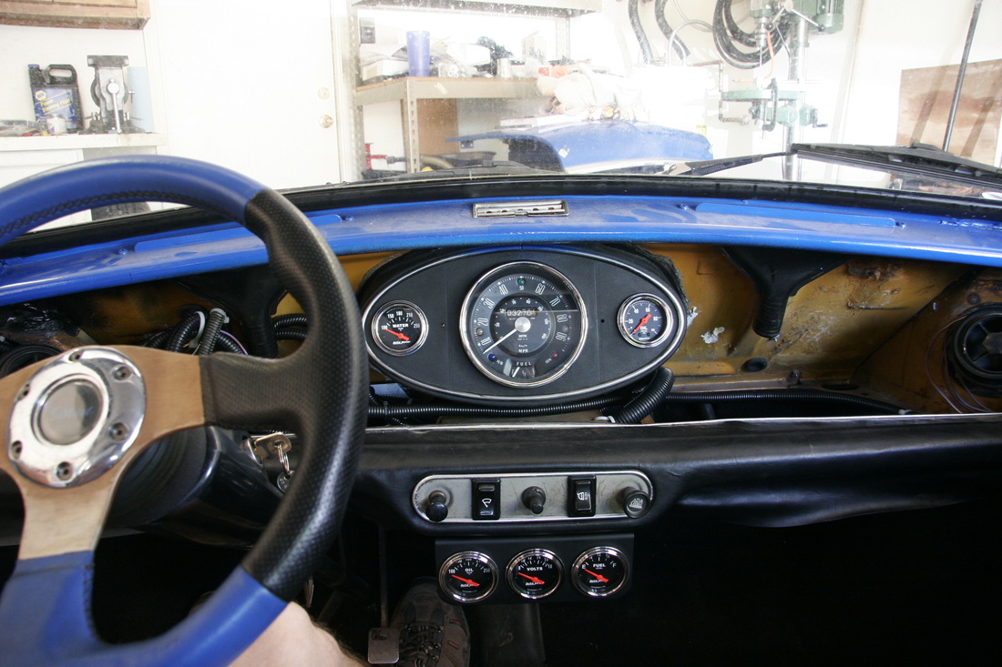
Here's another view of the nearly complete dash. At least the wiring is complete. Still TBD is the actual dash face.
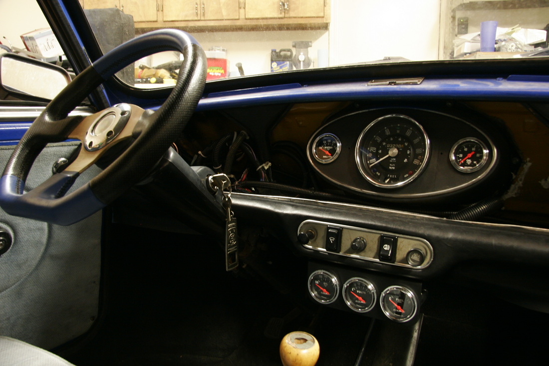
Daytime view of the dash from the passenger's perspective
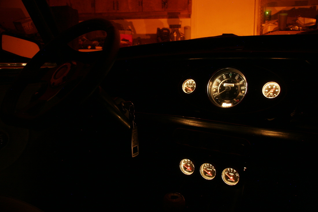
Night view of the dash from the passenger's perspective
