carb rebuild
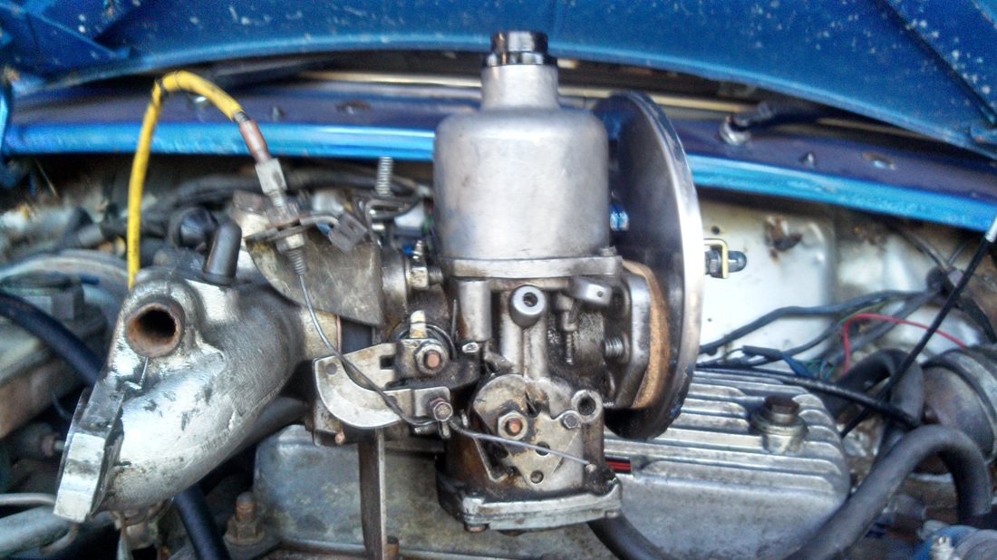
This tutorial will cover a servicing of an HIF 44 SU carb. To start, you will need an HIF 44 carb and the CSK 75 service kit which is available from a number of retailers.
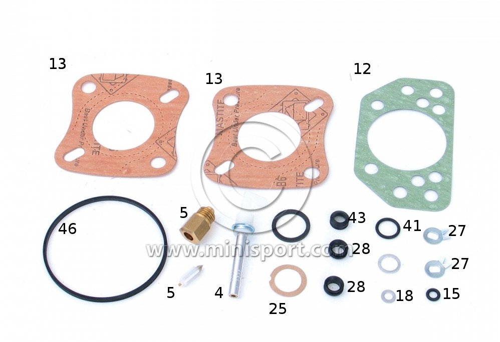
in the kit
I have tried to label the pieces to make it a little easier. This exploded diagram of the HIF 44 carb was copied from sucarb.co.uk and is the best I have found. Included is a list of the parts which I have tried to correlate to the below list of what you can kind in your kit. I wish I had taken a photo myself prior to using it, but I didn't, so I will have to settle for this one from Mini Sport. Some kits do seem to include additional items like different versions of 28 and a new 44. (These numbers are references from the diagram.)
teardown
Instructions from the official SU kit can be found on their website here. I used these for my project, but they weren't always the most transparent. Hopefully my rebuild will help someone.
I recommend you take photographs as often as is humanly possible. A part might fall out and you can't remember where it goes or you don't remember where that screw went. The more pictures you have, the more reference points you can use to undo any mistakes you may make. Remember, please use this tutorial at your own risk and I am not responsible for any mistakes you make.
I recommend you take photographs as often as is humanly possible. A part might fall out and you can't remember where it goes or you don't remember where that screw went. The more pictures you have, the more reference points you can use to undo any mistakes you may make. Remember, please use this tutorial at your own risk and I am not responsible for any mistakes you make.
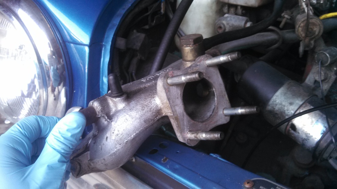
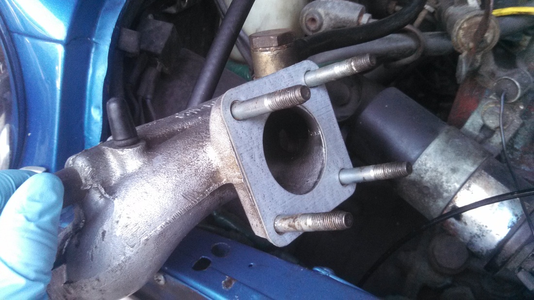
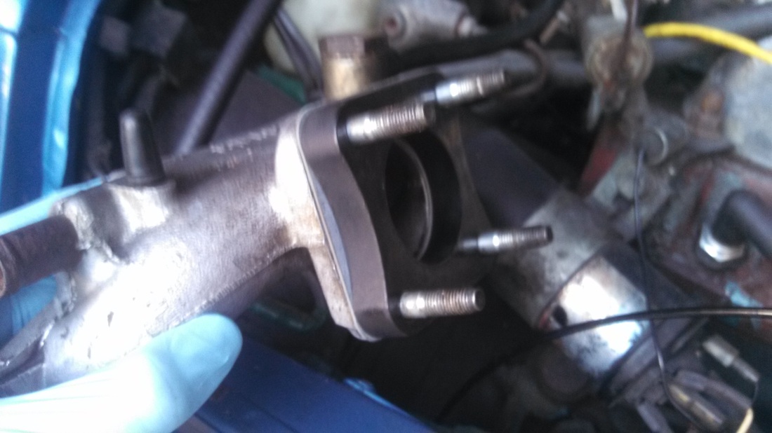
1. Remove the carburetor from the car. I thought the easiest way would be to remove it from the intake manifold but it proved easier to remove the intake manifold and the carb and then separate the carb from the manifold. You need to remove your air box (if fitted) and then undo the 4 nuts that hold the intake manifold to the head. If you car has a one piece intake/exhaust manifold, then you will have to remove the carb from the manifold.
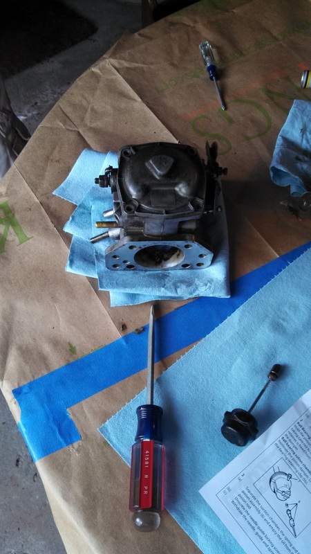
Tip: Take photos of your carb from both sides before you remove it to make sure you can reconnect it later. This is also a great time to clean any major oil and dirt off the outside of the carb. It helps keep your hands clean and stop contaminents from entering the carburetor later in the process.
Tip: Take photos of your carb from both sides before you remove it to make sure you can reconnect it later. This is also a great time to clean any major oil and dirt off the outside of the carb. It helps keep your hands clean and stop contaminents from entering the carburetor later in the process.
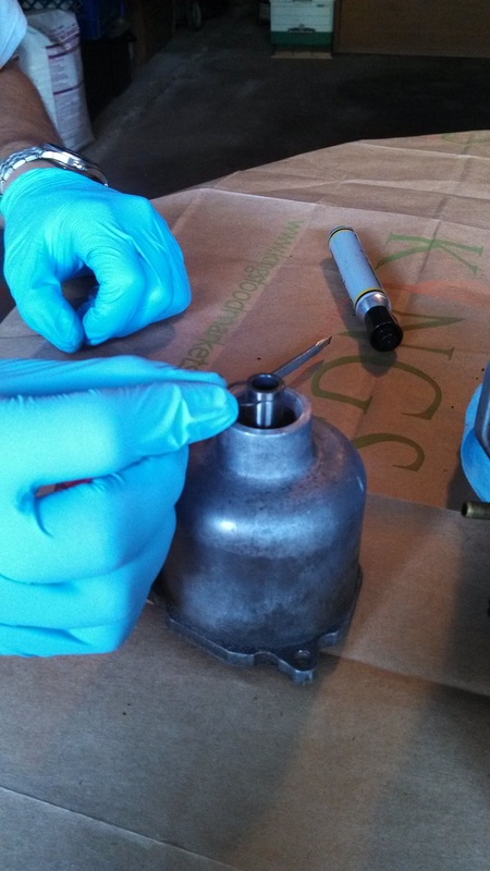
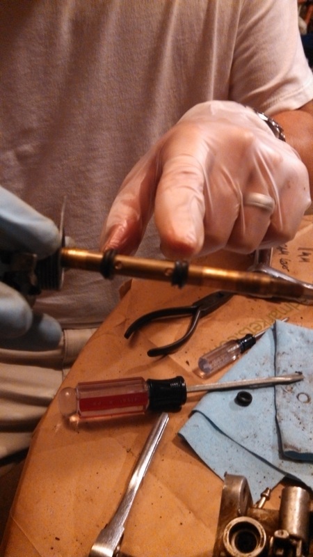
2. Unscrew the damper rod and set it aside. Remove the 3 screws that hold the damper to the carb body. Be careful when removing the assembly as the needle is sticking out off the bottom and you don't want to bend or break it.
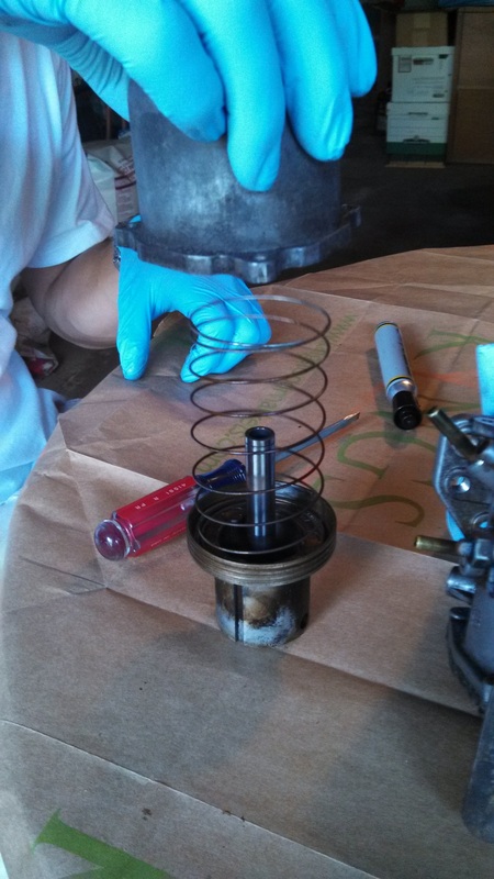
Remove the needle by undoing the lock screw in the side of the piston. Be careful when removing the needle as there is a spring on the top.
Now you can remove the circlip at the top of the rod. I found it was easiest to access this by resting the whole assembly on the table. This pushed the piston up into dashpot and exposes the top of the tube. Be careful when removing the clip that you don't bend or break it.
3. Once the circlip is removed, you can easily disassemble the damper. This particular kit didn't really include any pieces for the damper so disassembly isn't even necessary. I believe the extra o-ring in the kit can be used on the damper cap.
I took this opportunity to clean up the piston. REMEMBER, there is oil in the cylinder so if you tip over the damper, oil will spill on to your table, lap or anything else you have nearby.
I took this opportunity to clean up the piston. REMEMBER, there is oil in the cylinder so if you tip over the damper, oil will spill on to your table, lap or anything else you have nearby.
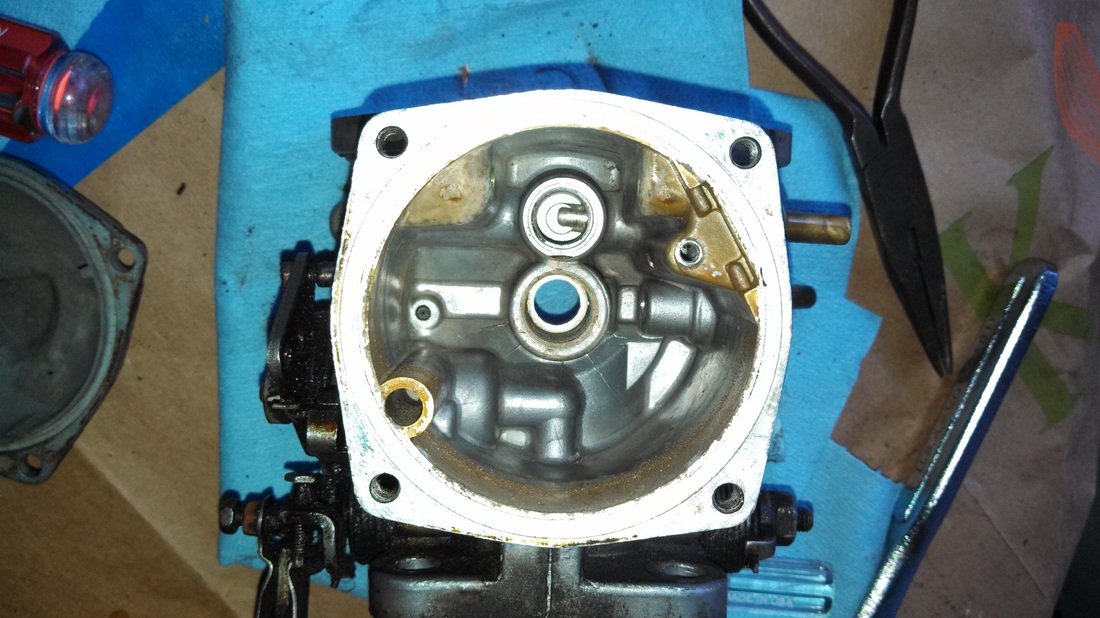
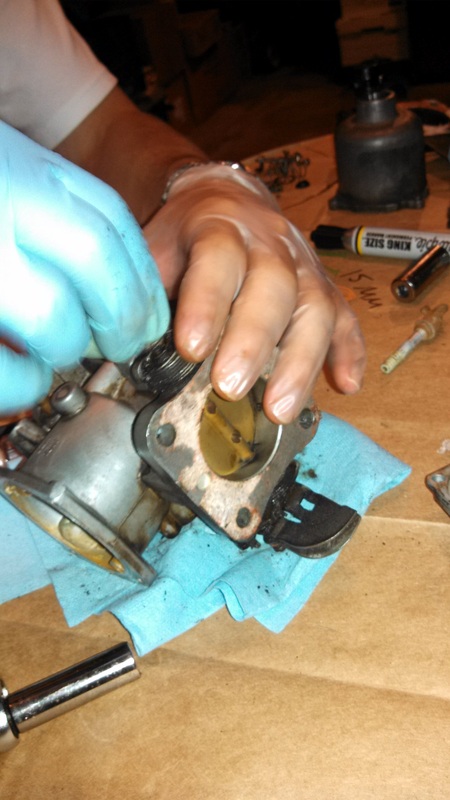
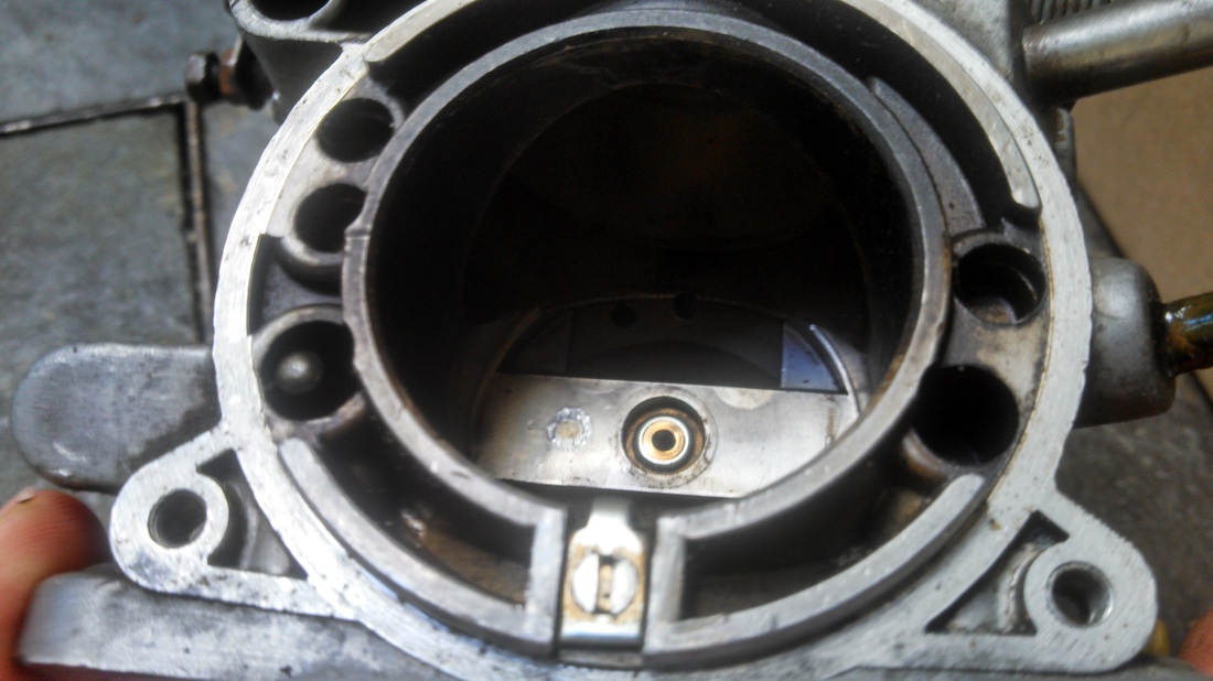
4. Flip the carburetor over and remove the 4 screws that hold the float lid on. There is a seal at the bottom that will be replaced with a new one from the kit. It was at this point I got a nasty surprise and found all kinds of gross stuff inside my float chamber.
The instructions recommend you mark the cover and the body so you can install the cover back in the same position. As with every step of this rebuild, we took lots of pictures so we didn't screw anything up. I think a picture is sufficient here because we wanted to clean the parts anyway.
NOTE: There will still be fuel in the float chamber when you go to flip it over. The will escape from the overflow pipe and the inlet pipe. Be prepared for this when you turn the carb over.
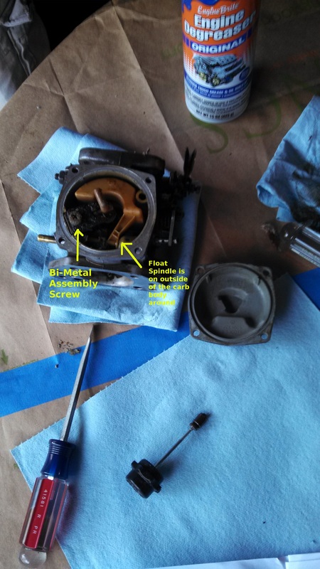
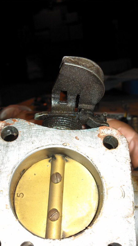
5. Remove the Jet mixture screw from the side of the carb. Remove the screw and spring that secure the bi-metal assembly. Remove the float spindle screw which is located on the outside of the carb body. The kit includes a new washer for the spindle.
In the picture you can see the underside of the float cover. The circle that runs around the inside contains a seal. There is a replacement in the kit.
In the picture you can see the underside of the float cover. The circle that runs around the inside contains a seal. There is a replacement in the kit.
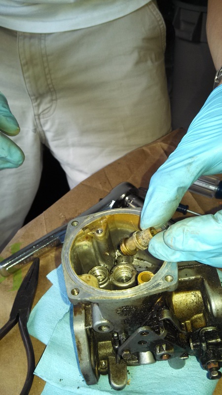
6. The next step was to remove the Jet assembly. There is a new one of these in the kit. I found mine did not move very freely and I had to pull it out with a pair of pliars.
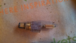
7. After removing the jet assembly, it was time to remove the needle and the needle seat. It's confusing since there are two parts called a needle. The needle just sits in the seat. Once you remove the float, there is nothing to stop it from falling out. The seat requires a socket set to remove. I found a 13mm socket worked quite well. It was a little stiff so just be aware. When you remove the seat, there is a little filter on the bottom. The service kit comes with a replacement for all 3 of these pieces.
Note the direction of needle in the needle seat. There is a tapered point on one end and the other end has a little spring loaded ball. The tapered end faces into the seat. The float will rest on the springy end.
Note the direction of needle in the needle seat. There is a tapered point on one end and the other end has a little spring loaded ball. The tapered end faces into the seat. The float will rest on the springy end.
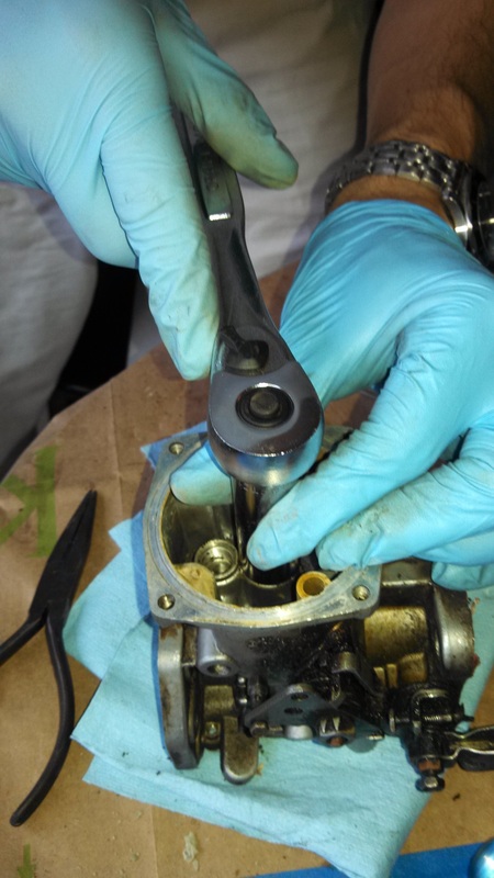
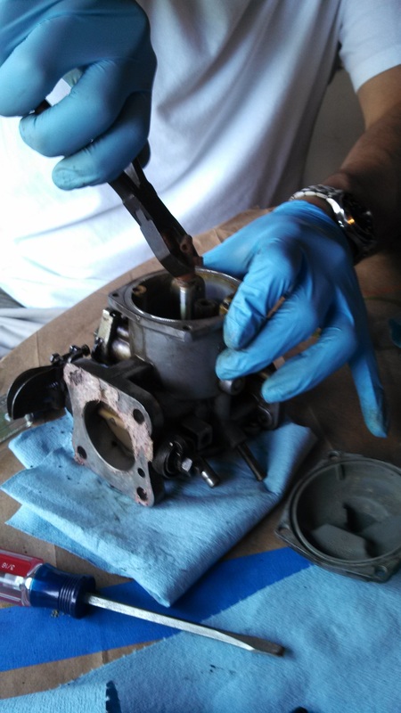
8. Remove the lock nut holding the jet bearing in place. This also requires the use of a 15mm socket and some force.
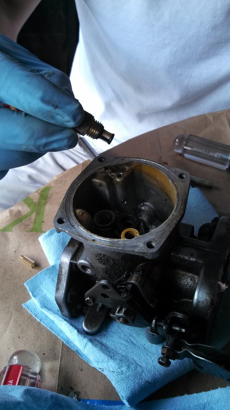
9. Pull out the jet bearing. All these parts should be cleaned.
10. It was at this point that I decided to clean out all the junk that was floating around inside my chamber. Since I don't have an air compressor, I used one of those cans of compressed air that you can get at office supply stores. It worked a treat and cleaned all the garbage out.
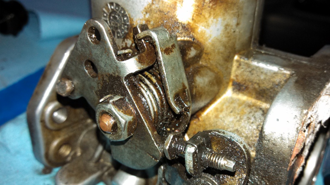
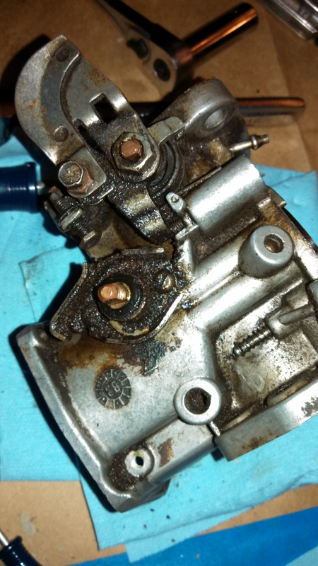
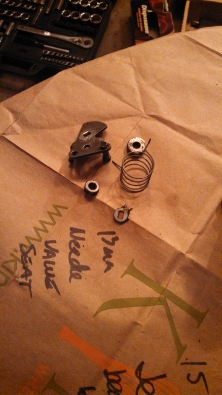
11. Next step is to remove the fast idle cam lever. This is the lever the choke controls. This requires removal of the tension spring. It is highly recommended that you take a lot of photos so you can ensure the spring goes back to the same place and that you tension it correctly. Bend back the tangs on the lock washer and remove the cam lever retaining nut. An 11mm socket should fit nicely.
This photo, besides showing all the filth on my carb, shows the nut and the lock washer tangs. The kit includes new ones.
This photo, besides showing all the filth on my carb, shows the nut and the lock washer tangs. The kit includes new ones.
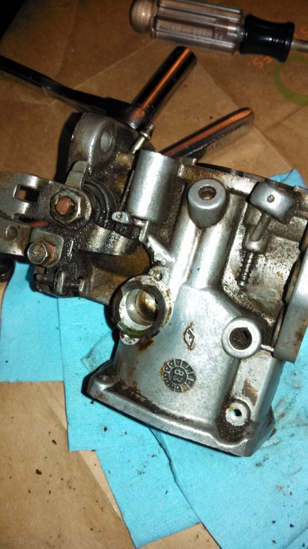
12. In order to remove the cam lever, I recommend holding the spring with a pair of pliers so as not to risk having the spring fly off and injure someone. After pulling off the lever and the spring, you are left with the starter body assembly. There is also a spindle seal and a little metal cover that has to be removed. Replacements for both these items are in the kit.
There are 2 screws securing the starter body assembly to the carb. Remove these and remove the assembly.
There are 2 screws securing the starter body assembly to the carb. Remove these and remove the assembly.
13. There is a small washer behind the assembly. It may be difficult to see at first, but scrape this away and remove the starter spindle. There is an o-ring at the end of the spindle that should be replaced with a new one in a kit.
The photo shows the washer, but the spindle has already been removed.
The photo shows the washer, but the spindle has already been removed.
14. Next is to remove the throttle spindle. There is a spring on both sides of the spindle, but the one on the side with the throttle lever is under more tension. It's for this reason that it's easier to undo the nut on the opposite side. Just like the fast idle lever, straighten the lock washer and then undo the nut. I had a second set of hands hold the spring while the nut was undone. This way the tension can be released slowly.
Tip: Just as before, take as many pictures as necessary so you can replace the spring exactly as it was previously.
Tip: Just as before, take as many pictures as necessary so you can replace the spring exactly as it was previously.
15. Before the spindle can be withdrawn, the throttle disc must be removed. Take pictures to note the orientation of the disc within the spindle. Undo the screws and then open the throttle. This will rotate the disc making it possible to withdraw it from the slot in the spindle.
Don't forget your pictures!
Don't forget your pictures!
16. After removing the throttle disc, the spindle is free to be removed. I used pliers to hold the tension on the spring so that once the throttle lever and spindle were clear, the tension could be released slowly. As you withdraw the spindle, the rubber seal on the outside will fall off. There are new seals in the kit. This is the last piece to be removed.
rebuild
Rebuilding the carb is just the reverse of tearing it down. The only modification I have heard is that some have recommended the use of a new seal and an old seal on the throttle spindle. The use of two seals helps ensure that the spindle is well and truly air tight. The new seal should be placed closet to the carb body with a second seal serving to take up an excess space.
Tip 1: When installing the new needle and needle seat, it is important they are in the correct order. The photo at the left shows the correct orientation.
Tip 2: When reinserting the starter body assembly, first replace the o-ring on the end. Then, before replacing the nut, do not forget the seal and the cap. These parts can be seen at the left.
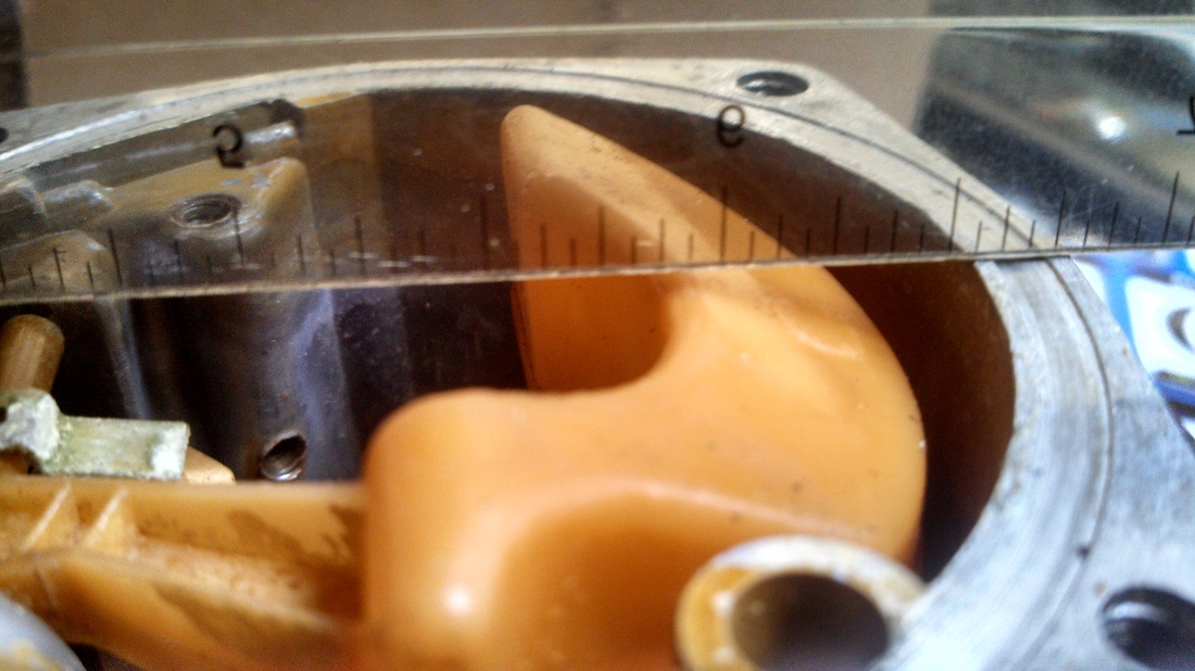
Tip 3: After replacing the float, you need to verify the spacing is correct. With the carb upside down and only gravity determining it's height, place a straight edge across the carb body at the lowest part of the float. There should be 1mm of space between the float and the straight edge. If necessary, adjust by bending the metal tab on the float.
Tip 4: After installing the new jet and bi-metallic assembly, it will be time to install the jet adjustment screw. The give yourself a decent starting point for adjusting the air/fuel mixture, get the jet level with the bridge and then go two turns clockwise to lower it about 1.25mm
reinstallation
Once everything is back together, it's just a case of putting everything back into the car. There are a few gaskets that need to be replaced. Before replacing any gaskets, use a razor to scrape away any remains of the old gaskets. You want to make sure you have nice, smooth mating surfaces. Here is the order mine went back in:
1. Clean surface
2. Gasket - This was not included in the kit and I had to order it seperately
3. Spacer
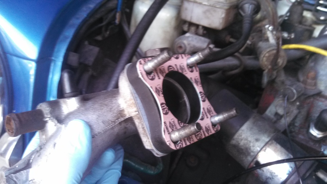
4. Gasket - This was included in the kit
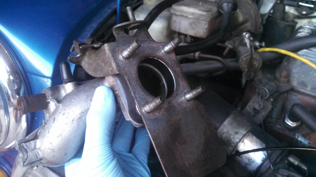
5. Plate - Make sure you get the orientation of this plate correct
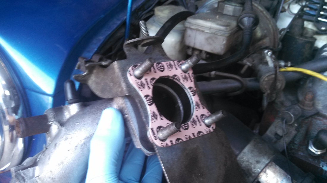
6. Gasket - This is the last gasket included in the kit
7. Carb!
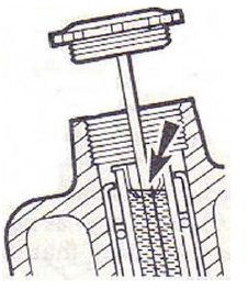
8. Replace the damper oil. Check this out for more information on the oil. Fill the inner damper tube like the diagram on the left indicates.
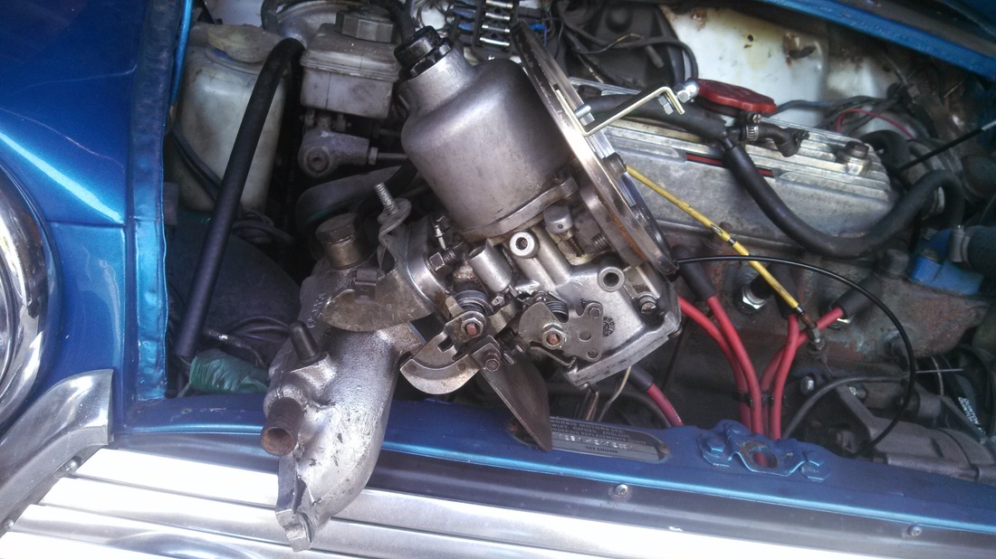
8. Bolt up the manifold and replace the fuel inlet hose, the breather, the fuel overflow hose, the throttle cable and the choke cable. Start the car up and make sure it still works. You may need to adjust the air/fuel ratio.
This is an original tutorial from http://classicmini.weebly.com
additional resources
For more information on rebuilding an HIF44 carb, here are a couple other sites with extremely useful information
http://www.turbominis.co.uk/forums/index.php?p=vt&tid=2878
http://www.turbo-mini.com/59247/59308.html
http://www.turbominis.co.uk/forums/index.php?p=vt&tid=2878
http://www.turbo-mini.com/59247/59308.html
